
Stargazer Extended Techniques Chapter 1: Sticking Your Fingers in the Electrical Socket
The expression pedal input on Stargazer can be used for more than just what it's labeled for. In the video above I demonstrate two simple controllers you can DIY at home for your Stargazer. The controllers, depicted in the video are two simple passive circuits. The first is a light sensor housed inside of a Stereo Audio (TRS) Plug. The second is a potentiometer housed inside of an Altoids tin,

Diagram courtesy of Strymon
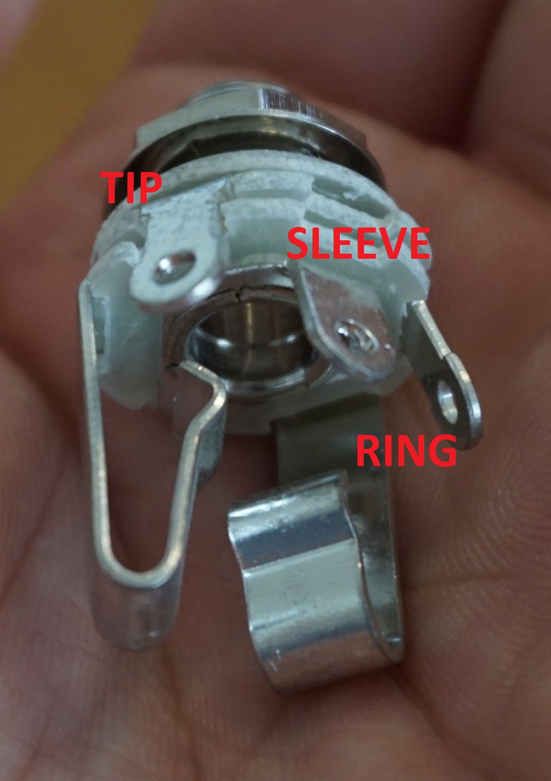
An expression pedal is a simple device. It is essentially just a potentiometer housed inside of a foot pedal. The role of the potentiometer inside the foot pedal is to function as a voltage divider. The expression pedal connects to a devices using a TRS cable rather than a typical 1/4" audio cable. The pinout is as follows: Tip - "send," Ring - "recieve," Sleeve - "ground." Sometimes "Tip" and "Ring" are opposite on different devices. This is how the polarity on an expression pedal can be flipped.

Voltage comes into the expression pedal from the "TIP" input and returns to Stargazer into the "RING" input. The change in value of the potentiometer affects the amount of voltage that gets returned to Stargazer. After the voltage comes back from the pedal it goes into a 1k resistor. This resistor limits current in the event of an accidental short and also is 1/3 of an over voltage clamp. The voltage clamp is created by the resistor and the two schottky diodes. What this node of the circuit says is "don't let anything pass higher than 3.3v and don't let anything pass lower than 0v). This feature is what protects stargazer from exploding when you start plugging stuff into the expression pedal input.
In this particular application, the voltage is then converted to digital messages using an analog to digital converter or ADC for short. This is why our pedal reference is 3.3v. Stargazer is digital and utilizes a low voltage micro controller.
We can start having fun by replacing the expression pedal potentiometer with a different voltage divider!

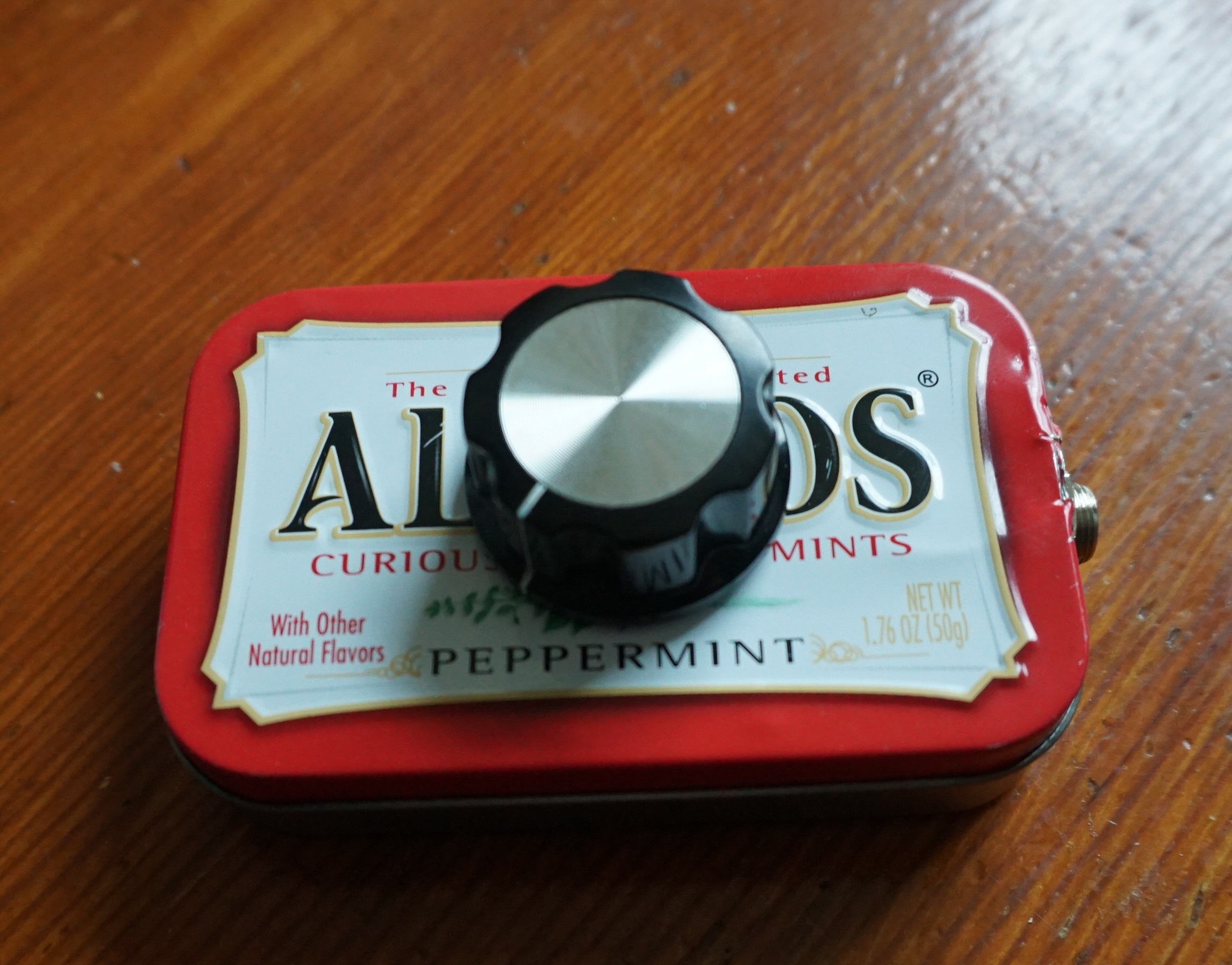
In our Altoids tin example, you'll see a potentiometer hooked up to a TRS jack but rather than being connected to a foot pedal, it just has a knob connected to it.
Pinout: Pin 1 - Sleeve, Pin 2 - Ring, Pin 3 - Tip.
If you flip pin 1 and pin 2 that will change the polarity of how the potentiometer behaves.


A voltage divider can be created by two resistors as well. A potentiometer is essentially just two resistors that you can change the value of by sweeping between the two poles. The two circuits below are functionally similar but the one on the left is fixed where as the one on the right can be changed by turning the potentiometer up and down.
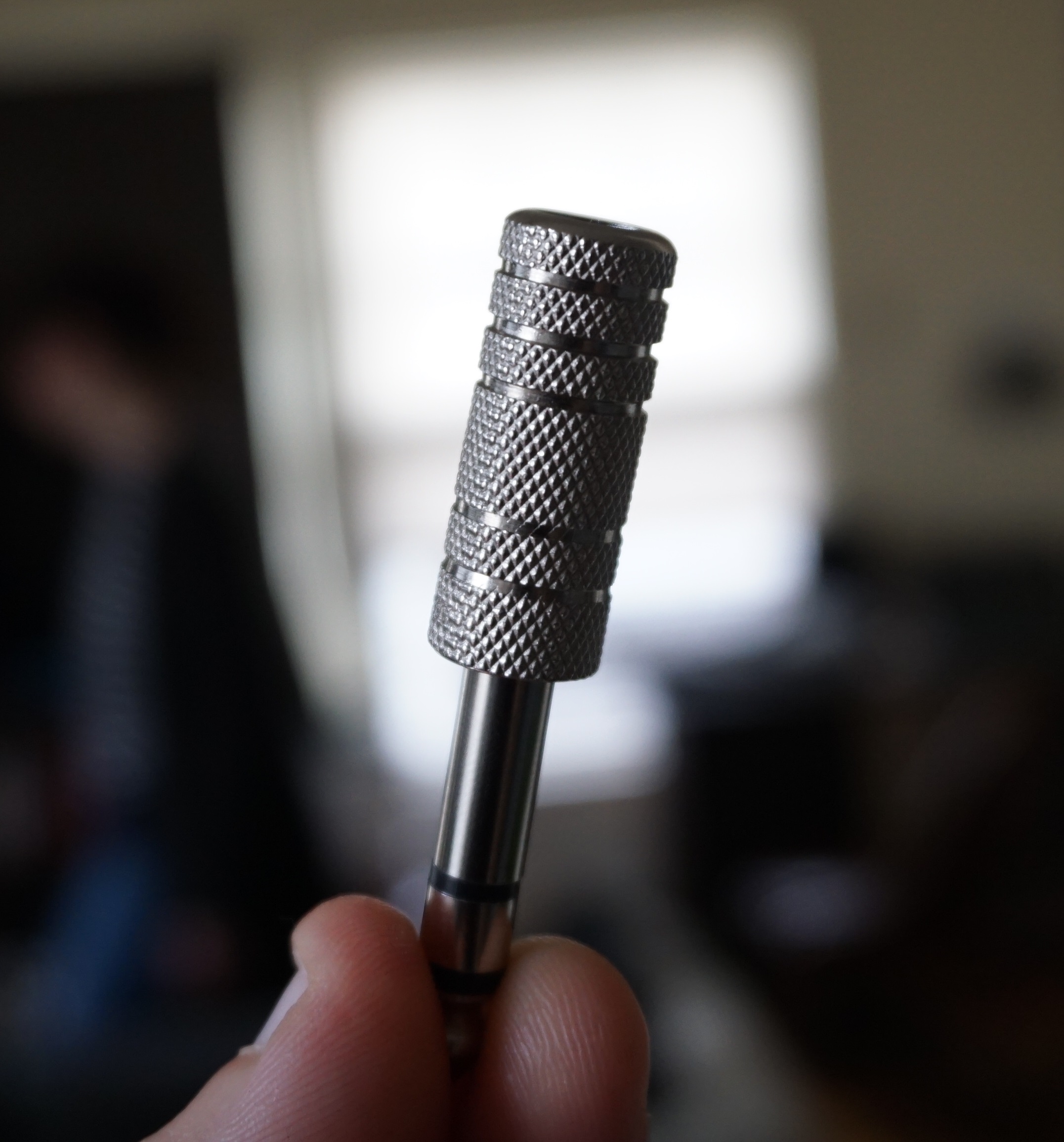
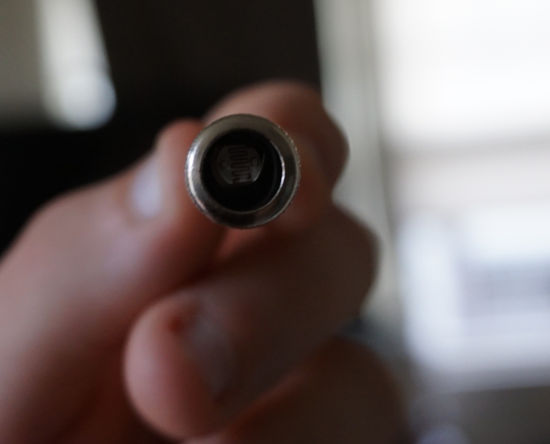
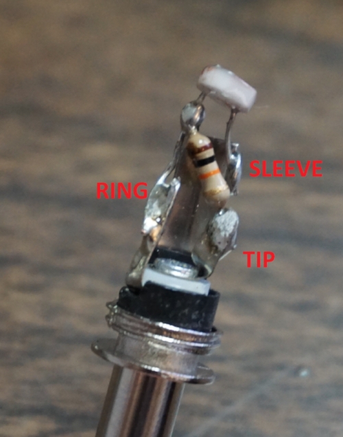
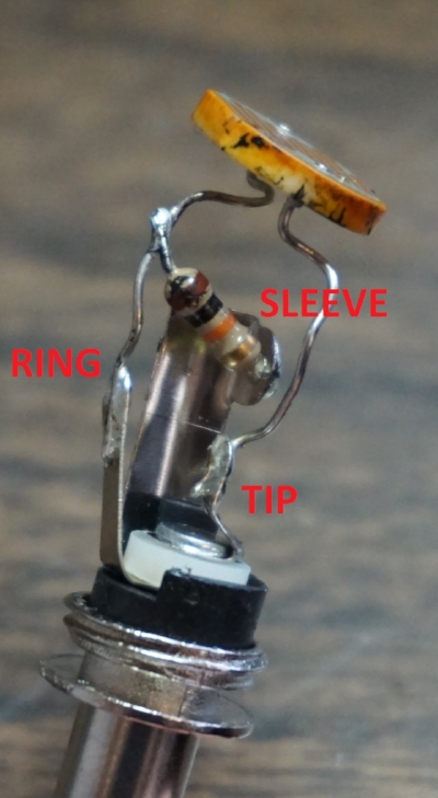
On the right is our completely barbaric hack with all of it's insulation torn open to show you that you can cram a photocell voltage divider into a TRS plug. The photocell and resistor function in the same way as fixed resistors or as a potentiometer. Much like the potentiometer example above, the polarity of the sensor can be adjusted based on which node you send the voltage and which node you send ground.

The photocell technique was originally showed to me in different form as a mod by Matthew Goodwin Akers. He had modded a digital delay pedal so that the potentiometer that controls the delay time would instead be controlled by a photo-resistor. In his particular application he only needed the single photocell and a 1/4" switched mono plug. With nothing plugged into the jack, the circuit normalized to using the onboard potentiometer. When you plugged in the photocell, it overrode the potentiometer and replaced it's point in the circuit. The potentiometer in that case was a "rheostat" or variable resistor rather than a voltage divider. Perhaps both methods may be of use to you on other projects in your future hacking. Give it a shot!

If you're a fancy pants and want to buy the bigger photocell with the high quality plug, get it from Digikey with the above part numbers.

If you're a cheap fuck and don't care about quality, get it from Tayda with the above part numbers. They only have the small photocells.